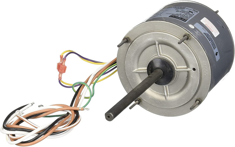
The Fasco motor leads are usually either numbered or color-coded for identification. There are variations in the color codings between manufacturers. It is recommended that you check the old motor first to make sure the existing wiring system is identified and diagrammed as it should be. If one is not present, you can make your own diagram at the time of disassembly.
Fasco PSC replacement motors contain two brown capacitor leads that aid in providing a simple hook-up. Of the two brown leads, one has a white tracer on it. This lead can be cut off and insulated but only when one capacitor lead is desired. It is common to see OEM applications with only one capacitor lead connected to the capacitor. The lead that is on the other side of the capacitor is usually the common one.
Typical Wiring Diagram for Shaded-Pole Motors
The following are standard wiring color codes that are used by Fasco and many other manufacturers for Shaded-Pole motors.
Typical Wiring Diagram for P.S.C. Motors
The Fasco permanent-split capacitor motors contain many different kinds of wiring arrangements. The standard for Fasco and many other manufacturers is as described below:
If there is a ground lead present, it will be green or green with a yellow tracer. The wiring diagram for all Fasco motors is usually printed on the motor nameplate.
It is possible to reverse rotation of Fasco electrically reversible models. You just need to switch the four external connectors; that is, two female receptors and two male plugs. It is not possible to plug the male plugs together. It is also not possible to plug the female receptors into each other since they will not be compatible. Each one of the plugs goes into each receptor. However, if the rotation is wrong you can simply reverse the plugs.
Nowadays, the Fasco reversing lead system consists of two yellow and two purple leads.
Always connect the common (white) lead to the power first while working with the multi-speed motors. Like color leads such as yellow to yellow and purple to purple usually give clockwise rotation at the end of the shaft. On the other hand, connecting unlike color leads will give a counterclockwise rotation at the shaft end.
If the original motor lacks two separate capacitor leads and the original wiring pattern that is desired, you can use a wiring diagram on any of the many Fasco motors.
Motor Wiring and Rotation Reversing
It is possible to reverse the rotation mechanically with certain Fasco fan models. The model will always contain the inherent feature of the stator being positioned exactly in the center of the motor. It is recommended that you inspect the Fasco fan motor on an individual basis. In those Fasco fan motors that contain thru-bolts, you can use the following procedures for reversing them:
- Loosen and remove the thru-bolts.
- Remove one end of the shield.
- Remove the stator, turn it around, and then insert it back to its original position. All the leads in the fan should be pulled through the available end shield ventilating openings.
- Replace the end shield, thru-bolts, and then re-tighten thru-bolts.
- Inspect to ensure that shaft turns freely. If you notice that the shaft is tight, tap the Fasco fan motor lightly using a non-metallic mallet. At times, it may be necessary to loosen and re-tighten thru-bolts. Always connect the white common lead to the power supply first when connecting multi-speed motors. The various speed leads go directly to the switching device.

